Obtain Accuracy and Position Control with Stepper Motors
Operation
A step motor is a motor type with a permanent magnet rotor and a stator wound with two independent windings. By alternating the direction of current flow through these windings, the motor will move in discrete “steps”. The size of the step varies with the construction of the motor. The commonly available range is from 18 degrees of shaft rotation per step, down to 0.9 degrees of rotation per step. With the help of a step motor controller, accurate speed and position control can be attained.
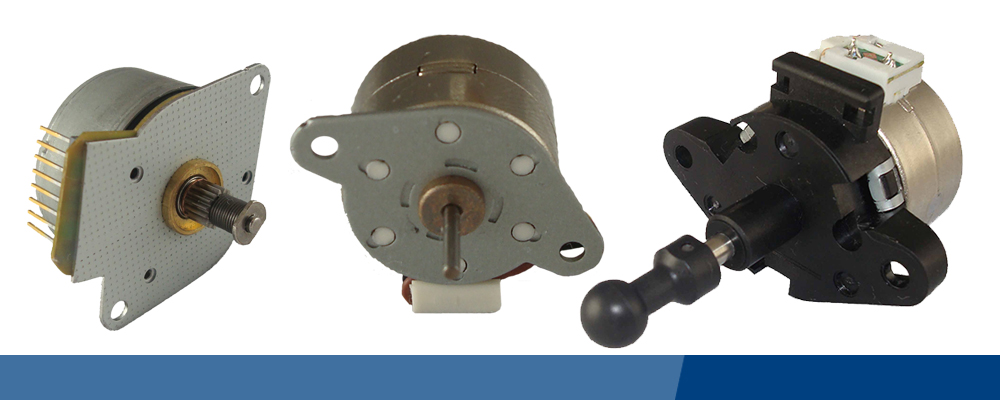
There are two basic types of step motor. The PM (permanent magnet) motor, sometimes called a “tin can” step motor is inexpensive to produce. The “tin can” name comes from the fact that the rotor and the outer housing are formed from stamped steel parts. They are available in sizes ranging from 10mm to 55mm and step angles ranging from 3.75 degrees/step to 18 degrees/step. Often, a low cost spur gearhead is added to provide higher torque at lower speeds.
The hybrid step motor uses a different construction method to provide for smaller step angles. Typically, they are available in 1.8 degree/step or 0.9 degree/step configurations. They provide very high torque for their size and a high level of accuracy and repeatability. These are most commonly available in NEMA frame sizes ranging from 08 to 42. They are more expensive than PM stepper motors, but better suited to applications requiring high torque and accurate positioning.
Controllers and Drivers
Unlike some motor types, stepper motors require electronic control for operation. This consists of two parts. The “controller” contains the program that controls the speed and number of steps. It can be programmed to provide automated control of a complex sequence of motor movement. There is also a “driver”, or power section, that controls the actual magnitude and direction of the current flow to each of the two phase windings. These two parts may be contained in a single unit, or they can be split into separate units. In multi-axis application, a single controller may control several drivers and motors.
Nearly all drivers provide switching patterns that can cause the motor to rotate in “Full” or “Half” steps. In full step mode, the motor rotates in increments of its basic step size. In half step mode, it would move half this distance per step. In other words, a motor with an 18 degree/step construction would move 9 degrees/step in half step mode.
To get even finer movements, a micro stepping controller can be used. These provide a more complex switching pattern that can allow for much finer step sizes. With a micro stepping controller, very fine movements are possible.
Unlike servo motors, which require rotor position feedback and monitoring, step motors operate in an open loop mode. This keeps the cost of both the motor and control electronics down.
All in all, stepper motors are a great choice in situations where accurate speed and/or position control is required. They are at their best in relatively low speed and high torque applications.
Power Electric works with OEM manufacturing companies throughout the US assisting customers with stepper motor solutions for their unique requirements. Connect with our in-house engineering experts for custom electric gear motors or find support choosing the right product for your OEM applications by calling 763-383-6936.
3121
Check out our new motor performance calculators!

 Request a Quote